

Not every engineering idea that takes decades to reach practical use is a failed idea. Some arrive before the necessary materials, manufacturing methods and control systems are ready.
Cycloidal propulsion is a particularly revealing example. Investigated for more than a century, it can generate thrust whose direction changes without tilting the rotor axis. It established a place in marine manoeuvring but never achieved the same adoption in aviation.
The obstacle was not a fundamental inability to generate force. It was the combined challenge of dynamic loads, blade-pitch actuation, complex unsteady aerodynamics, useful energy conversion, weight and operational reliability.
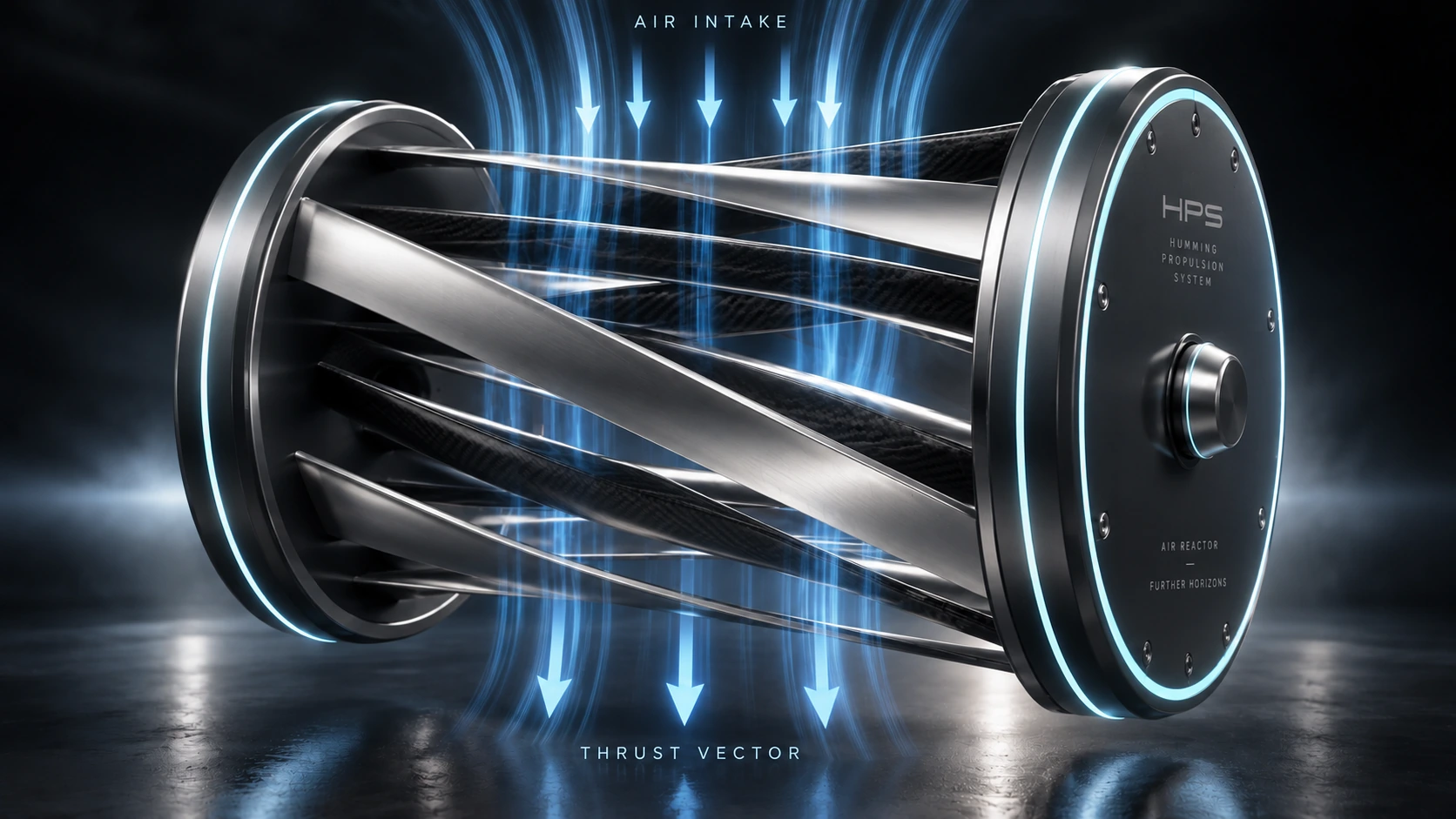
That is where our work at HPS Aviation began. We did not set out to claim a newly discovered physical principle. We studied a known one, the obstacles to applying it at scale, and the possibility of a different engineering architecture. Our ongoing result is the Humming Propulsion System, built around the Air Reactor concept
What distinguishes a cyclorotor from a conventional propeller?
A conventional propeller turns blades about an axis that generally aligns with the thrust direction. Redirecting that force substantially may require a tilting propulsor or other aerodynamic controls.
In a cyclorotor, blades travel around a circular path with their spans parallel to the rotor axis, changing pitch cyclically. Adjusting the phase of this motion redirects the resultant aerodynamic force.
The thrust vector can therefore be directed through 360 degrees in the plane perpendicular to the shaft without tilting the entire unit. This is inherent to cycloidal propulsion; HPS does not claim to have invented it.
A vectorable rotor does not, by itself, confer six-degree-of-freedom control on an aircraft. That depends on propulsor placement, allocation of forces and moments, and an integrated flight-control system. The challenge is making this promising property operationally useful
Why has cycloidal propulsion remained uncommon in aviation?
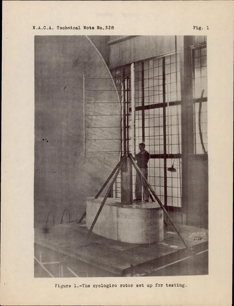
Work ranging from Kirsten–Boeing experiments in the 1920s to modern cyclocopters has demonstrated the principle and exposed demanding engineering trade-offs.
There is no single variable that can be optimised independently. Mechanics, aerodynamics, controls, mass and service life interact. A solution suited to a small research demonstrator may be far less suitable for a larger propulsor expected to operate reliably on a crewed aircraft
Blade-pitch accuracy and mechanical complexity
Cyclorotor blades must both revolve about the main axis and vary pitch in a precise relationship with angular position. The actuation mechanism must sustain that repeated motion under high speeds and changing loads.
Timing accuracy, component stiffness, clearances and wear increasingly affect performance and reliability. Both mechanical linkages and individually actuated concepts have been studied, each with trade-offs. Combining precision, low mass, response speed and service life remains a central engineering challenge
Dynamic loads and fatigue
Blades experience centrifugal loading and aerodynamic forces that vary through every revolution. The repeated cycles affect blades, bearings, pitch mechanisms and their supporting structure.
The challenge extends beyond surviving a peak load: the system must manage fatigue, vibration and deformation over operating life. Enlarging or accelerating a rotor is therefore not a simple route to greater thrust; it changes the internal load paths that must be engineered
Unsteady aerodynamic interactions
A cyclorotor blade does not move through a uniform, static flow. Relative velocity, inflow direction and effective angle of attack change throughout a revolution, and each blade may encounter the wake left by others.
Unsteady flow separation, dynamic stall and blade–wake interaction can increase force in certain conditions or produce losses and vibration in others.
Not every vortex is waste, and not every interaction is beneficial. Outcomes depend on flow state, timing and geometry; they require analysis and measurement under the intended operating conditions
Efficiency, size and weight
Cyclorotors may compare favourably with propellers under particular conditions, but no blanket efficiency advantage is established across all missions. Geometry, speed, blade pitch, mechanical losses and wake interactions all matter.
An aircraft propulsor must balance thrust, electrical input, mass, packaging, noise, response and maintenance. Improving one variable can compromise another. Moving from principle to an operational product demands system-level trade-offs rather than aerodynamic performance alone
From cyclorotor to Air Reactor
We did not begin by asking how to build another cyclorotor. We began with the requirements of vehicles intended for vertical take-off and landing, accurate manoeuvring and thrust direction changes without tilting the entire propulsion installation.
This led us to reconsider unit architecture. Rather than treating each rotor solely as an independent force source, we began examining the moving air as a flow whose state can be influenced through consecutive stages. That is the basis of the Air Reactor concept
Interacting stages rather than an isolated stage
The HPS architecture uses successive annular stages. Downstream stages receive air already affected by upstream motion, carrying velocity, direction, pressure distribution and vortical structures.
The engineering question shifts from how much force an individual rotor can produce to how momentum and energy pass between stages, and whether that interaction can improve the whole unit.
Adding stages does not automatically improve efficiency; it can introduce further losses. Our aim is to coordinate those interactions deliberately, with testing—not architecture alone—determining the actual benefit
Counter-rotation and torque management
Our design uses counter-rotating stages, providing options to manage rotational moments and redistribute mechanical and aerodynamic effects. It also changes how successive stages encounter the flow.
Counter-rotation does not automatically cancel vibration or torque. The result depends on balance, speed, geometry and load transfer. We therefore develop mechanics, aerodynamics and control together rather than as isolated problems
Blade support and load paths
HPS uses blades supported at both ends to establish a different load path into the supporting structure. Composite materials help balance stiffness, strength and mass.
The design targets reduced deformation and more predictable motion under varying loads, while introducing its own bearing, alignment and assembly requirements. It is one element of an integrated mechanical architecture—not a universal solution to rotor loading
Coordinated multi-stage control
A cyclorotor's thrust direction depends on pitch phase, while magnitude depends on factors including speed, pitch amplitude and inflow. A multi-stage arrangement adds relationships between stages.
Relative timing, speed, angle of attack and flow state can affect the combined result. It is not enough for individual stages to operate well if their interactions degrade total performance.
Control development is therefore part of the aerodynamic and mechanical design itself rather than a feature added once the hardware is complete
What has HPS demonstrated?
Our research and development spans more than eleven years and five physical generations, leading to the sixth generation now in development. These were not simply changes in appearance; each generation explored practical questions about loads, motion, control, manufacture and testing.
We investigated both mechanical and electrical pitch-control approaches and revised our design path in response to what implementation revealed. In March 2026, the fifth-generation single-stage configuration was tested on the physical rig, providing evidence for that particular mechanism and test configuration.
Generation six, under development since June 2026, brings accumulated knowledge into a multi-stage architecture for integrated-unit validation.
We distinguish between established physical principles, solutions implemented and tested on particular prototypes, and target properties still needing verification. Demonstrating thrust on a rig does not by itself establish system efficiency, acoustic performance or long-term reliability
Is HPS separate from cycloidal propulsion?
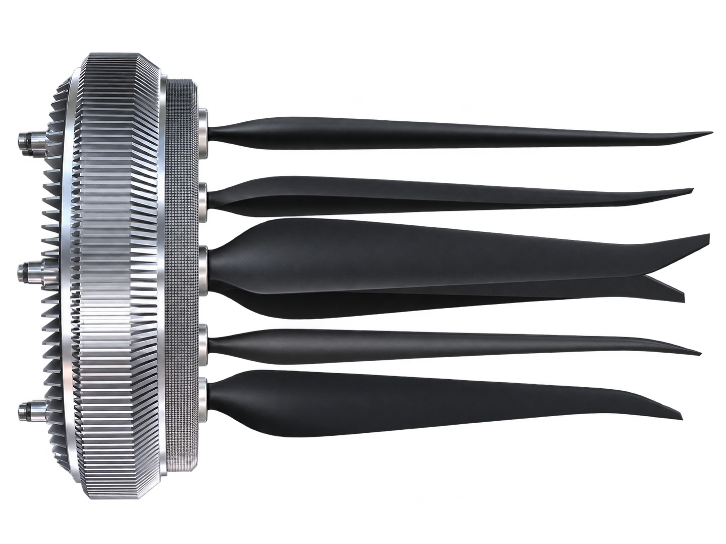
At the level of physical principle—rotating blades with cyclic pitch—Humming Propulsion belongs to the cycloidal propulsion family.
At the level of architecture, interacting stages, counter-rotation, load distribution and coordinated control, HPS develops its own engineering solutions. We present neither a break from cycloidal history nor a simple reproduction of an earlier design.
The distinction we seek is not thrust vectoring alone, which already exists, but a compact, coordinated multi-stage system suitable for vehicle integration. Its relative advantage must be demonstrated by comparative tests
The future of cycloidal propulsion
Advances in composites, electric motors, digital control, modelling and manufacturing have renewed interest in cycloidal propulsion. Demonstrations are no longer confined to very small prototypes.
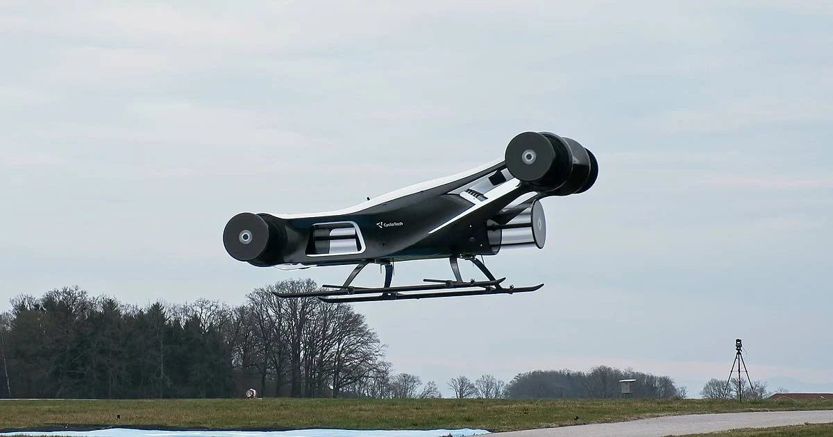
On 27 March 2025, Austria's CycloTech announced the maiden flight of BlackBird, a demonstrator weighing approximately 340 kg and fitted with six cycloidal propulsion units. It was an important step, but not proof that commercially certified crewed aircraft are already assured.
Future competition will turn on energy efficiency, reliability, safety and fault handling, noise, manufacturing and maintenance costs, and certification. Different architectures may suit different missions; no single design need dominate every operating condition
The Air Reactor and the TANNANA family
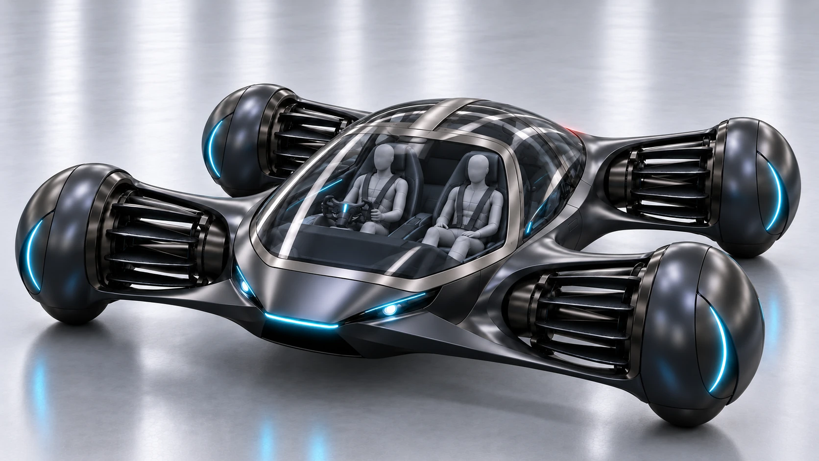
We do not develop Humming Propulsion independently of the vehicles it is meant to serve. We are building the TANNANA family around it, beginning with the CROW concept.
Our targets combine vertical take-off and landing, forward movement and precise manoeuvring without tilting the complete propulsion unit. Air Reactor success must therefore be measured in aircraft-level terms: mass, packaging, controls, safety and integration, not thrust alone.
Our next steps are generation-six ground validation, followed by a four-unit uncrewed flying demonstrator targeted for 2027. We target a crewed prototype and technical readiness to enter a certification programme by 2030, subject to test results, funding, resources and regulatory requirements. These are development targets, not confirmed certification or service dates.
If the architecture demonstrates its intended properties, it may support platforms of different scales and missions. Turning those possibilities into products will require a separate evidence and approval programme for each application
A continuing engineering history
Progress does not always begin with a newly discovered principle. Many transformative technologies grew from established foundations, with the advance coming from understanding their limitations and developing ways to overcome them.
This is where HPS stands in cycloidal propulsion history. We do not begin from zero, and we acknowledge those whose research and engineering preceded us. We build on that knowledge and on more than eleven years of our own design, manufacturing and testing.
Cycloidal propulsion is our physical starting point. The Air Reactor is the engineering architecture we are developing. TANNANA is the aircraft family through which we aim to demonstrate its practical value.
Many tests and challenges remain, but we now understand far more than when we began. The value of years spent in engineering lies not in their number alone, but in the knowledge they leave for the work that follows
Sources and further reading
This content was reviewed and approved for publication by HPS Aviation. Detailed test data is available to qualified investors and partners under NDA
More from this author
 Can the Roadster go further?
 The hummingbird: a question about moving air
Article discussion
Start the discussion with a question or an idea.
Sign in to commentReport an abusive comment